
- ARDUINO RGB LED TEST HOW TO
- ARDUINO RGB LED TEST FULL
- ARDUINO RGB LED TEST CODE
- ARDUINO RGB LED TEST SERIES
For example a simple and quick modification could be using 6 pushbuttons to have full control on the brightness value of each colour component (3 pushbuttons to increase the brightness of the 3 colours and 3 pushbuttons to decrease it).
ARDUINO RGB LED TEST HOW TO
Obviously this is just a simple project aimed to show you how to control an RGB LED, but it should be quite easy to extend it and to use it as a starting point for more interesting experiments with RGB LEDs. For example pushing the first and the second buttons makes yellow, pushing the first and the third buttons makes fuchsia, etc. Pushing more buttons at the same time allows you to get even more colours. Pushing a single button will increase gradually the brightness of the corresponding colour channel until it will reach its maximum brightness, which basically means you get a Red, a Green or a Blue light.

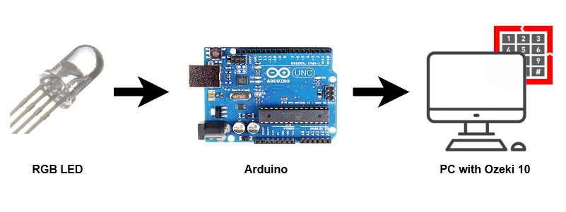
In this project I’m going to control an 5mm RGB LED using three pushbuttons and an Arduino Uno.Įvery pushbutton is controlling a colour channel of the LED, i.e: the first button is controlling the Red channel, the second button is controlling the Green channel and the third button is controlling the Blue channel.
ARDUINO RGB LED TEST SERIES
Once looped, it will change to the next colour and repeat.In this simple project I’m going to show you how to control an RGB LED (common anode) using an Arduino Uno and few push-buttons. 5V RGB Programmable COB LED Strip (50cm) Arduino Wiki - DFRobot How to select series How it works series Development Boards DFR0049 Analog Gas Sensor (QM-NG1) DFR0100 DFRduino Beginner Kit For Arduino V3 DFR0133 X-Board DFR0162 X-Board V2 DFR0188 Flymaple V1.1 DFR0182 Wirless GamePad V2. The program selects a colour and lights each LED in order. Connect the Arduino ground to the ground rail. Connect the power rail to the +12v connector of the LED strip (note that in this image the power wire is black to match the colors of the connectors on my LED strip). Connect the Drain legs to the Green, Red, and Blue connectors on the LED strip.
ARDUINO RGB LED TEST CODE
Load the code below into the Arduino IDE and upload it to your board.Ī simple program designed to setup and demonstrate the 8 RGB LED Line Module - BBAA100005 Connect the Source legs to the ground rail. It then waits for a 100ms before setting the LED select back to HIGH and moving to the next LED. The loop sets both the colour and LED select pin to LOW, triggering the LED. The outer loop controls the colour pin selected and the inner one selects a particular LED in the array. It is made up of two loops, one nested inside the other. The Atmega328 chip can be programmed using the Arduino platform, we have used the DIP package of the. The loop contains the control program that will run continuously after the setup. Example Arduino code will help you to test the board. The setup defines the pins to be used in the control of the module. The code consists of the a setup and loop. I have used characters as '0, 1, 2, 3' for turning the led on and off for Red, green and blue colors. Using a 5050 RGB LED, by adjusting a PWM signal on the three primary colours the user can gain the full colour spectrum. Wire the two boards together as can be seen in the image below, taking care to match the pin numbers. I want the initial value of all LED color to be low. 12pcs Male to Female Jumper Cables - GBAA100002.1pcs 8 RGB LED Line Module Keyes - BBAA100005.1pcs Arduino UNO or Compatible - LCAA100005.

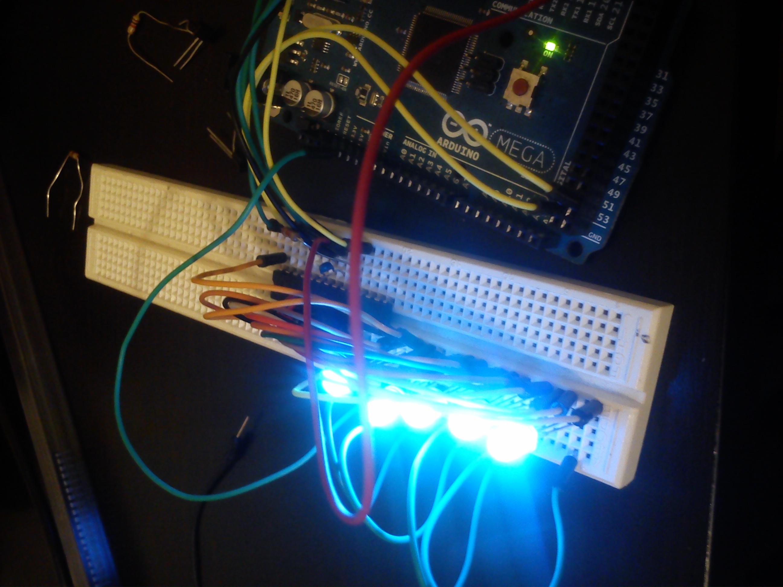
Once connected and the program loaded, the LEDs will cycle through the 3 individual colours of each LED in sequence, looping endlessly. This example will demonstrate the use of an Arduino UNO in the control of the 8 RGB LED module. Hopefully it will provide you with the confidence to push on to more advanced visual displays. Here is a quick introduction to using the Keyes 8 RGB LED line module.


 0 kommentar(er)
